FCOM A320 Aircraft Limitation
- Ariarso Mahdi Hadinoto

- Sep 17, 2024
- 9 min read
Introduction
The FCOM contains operational limitations, related to the aircraft and associated system, All references to airspeed, Mach, and altitude related to indicated airspeed, indicated mach, and pressure altitude.
The A320 aircraft must be operated in compliance with the limitations given in the Airplane Flight Manual (AFM). The A320 aircraft is certified in the public transport category (passengers and freight) for day and night operations, in the following conditions, when the appropriate equipment and instruments required by the airworthiness and operating regulations are approved, installed, and in an operable condition:
VFR and IFR
Extended overwater flight
Flight in icing conditions.
The minimum flight crew required to operate the A320 aircraft: is 2 pilots.
FLIGHT MANEUVERING LOAD ACCELERATION LIMITS
Clean Configuration....-1.0 G to 2.5 G
Other Configuration...0 g to 2.0 G
This is to ensure not exceed the structural load limit, and that the aircraft will remain and not exceed stress limit
This relates to the control law, which is the relationship between the pilot input on the sidestick and the aircraft response, which is called law.
The Types of Law:
Normal Law,
Alternate Law (With or without reduced protection),
Direct Law and
Mechanical Law
The Load Acceleration limit is the load factor manufacture limit to protect the aircraft incorporated with the LAW. When the LAW is degraded for example: the loss of one computer system, or source of power generation the aircraft will do the reconfiguration law as stated in FCOM.
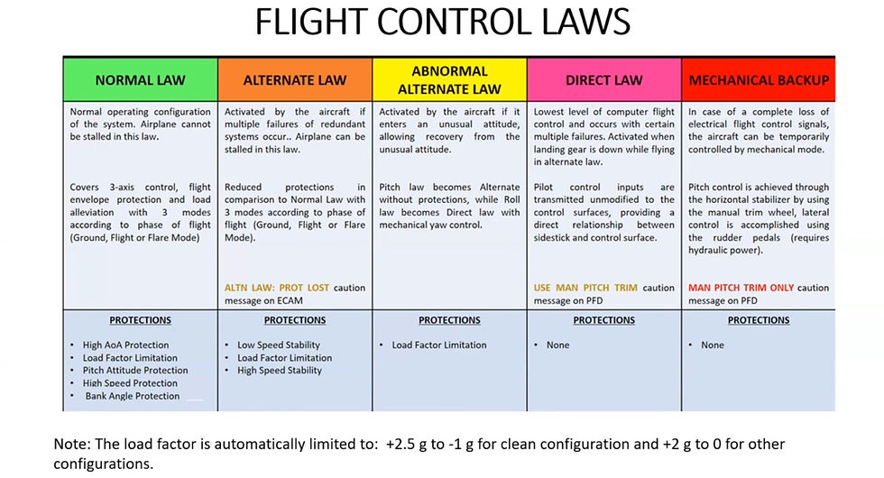

Reference to the table above :
Normal Law: Double Green thick mark
Alternate Law: X Amber mark
Direct Law: X Amber mark and "USE MAN PITCH TRIM"
Mechanical Backup: MAN PITCH TRIM ONLY
Note: The Speed Tape will change as indicated on Alternate Law and Direct Law compared to the Normal Law
ENVIRONMENTAL ENVELOPE
Maximum Pressure Altitude for Aircraft flying FL 39.800 feet
Maximum Airport Elevation for take-off is 9200 feet
The Minimum Airport Elevation for landing is -1000 feet and depending on the aircraft serial number some is -2000 feet
AIRPORT OPERATIONS AND WIND LIMITATIONS
Runway Slope
Runway slope (mean)........+/- 2 %
The slope of a runway, or gradient, is the difference in elevation from the beginning to the end of the runway. Pilots use the slope, along with headwinds and tailwinds, to determine the speed needed for a successful takeoff and for a safe landing. Knowing the slope of a runway allows for an experienced pilot to maximize the effective length of the runway, and to successfully maneuver his craft on an incline or decline.
Subtract the elevation of the lower end of the runway from the higher end. For example, if the elevation of the higher end of the runway is 4,400 feet, and the lower end of the runway is 4,370 feet, then subtracting 4,000 by 4,3700 results in 30 feet.
Divide the difference of the elevations by the length of the runway. For example, the length of the runway is 3,000 feet. Dividing 30 by 3,000 results in 0.01.
The Flight Safety Foundation's "Approach and Landing Accident Reduction Tool Kit" (ALAR) provides some guidance:
Wet Runways: Multiply the landing distance by a factor of 1.3 to 1.4
Standing Water or Slush: Multiply by 2.0 to 2.3
Snow-Covered Runways: Multiply by 1.6 to 1.7
Icy Runways: The landing distance could be 3.5 to 4.5 times longer than normal
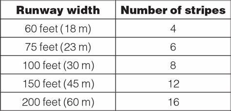
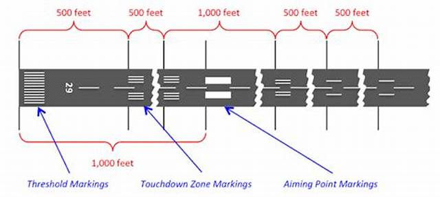
NOMINAL RUNWAY WIDTH
Nominal Runway Nominal Width ....45 M
This ensures that the 180 deg turn to back taxi
Minimal Runway width.......30 M
WIND LIMITATION
Maximum certified crosswind :
Take Off.....38 knots (including gust)
Landing.....38 knots (including gust)
Note: The Maximum certified crosswind for take off and landing is not an airplane manual (AFM) limitation: It's the maximum crosswind condition experienced during the aircraft certification campaign. Airbus recommended that operations should not intentionally operate in crosswinds that exceed this value.
In some aircraft, the newer model is limited to 35 knots, this is engine limitation.
This is based on reporting from the tower wind and ATIS
Maximum Tailwind :
Take off ...15 knots (including gust), some aircraft have 10 knots (including gust)
Landing ...15 knots (including gust), some aircraft have 10 knots (including gust)
Note: For Landing with a tailwind greater than 10 knots, use FLAP FULL Only.
Maximum Wind For Door Operation
Passenger door operation.....65 knots
FWD and AFT cargo door operation....40 knots
(or 50 knots, if the aircraft nose is into the wind, or if the cargo doors are on the leeward side)
FWD and AFT cargo doors must be closed before wind speed exceeds 65 knots.
Maximum Crosswind on Contamination Runway
This is not part of the limitation, due to the essential information given pilot for approach-landing and take-off, the pilot recommended memorizing the value.

RWYCCs have been designed to be a simple and effective means of enhancing pilot situational awareness by clearly and concisely indicating how slippery the various sections of a runway are. In addition, they provide a significant safety advancement since they align with airplane performance data (information) that can be used for the time-of-arrival landing performance assessment.
A great deal of thought and research by industry experts has gone into the development of RWYCCs and the RCAM; these are powerful tools that are intended to help mitigate the hazards and risks associated with landings on wet and contaminated runways.
COCKPIT WINDOWS OPEN SPEED
Maximum Speed....200 knots
Maximum Flaps / Slats Speeds

Maximum Operating Speed VMO/MMO
VMO ... 350 knots
MMO.. M.82 Mach
The change over speed from VMO to MMO at FL 250
Maximum Speed With the Landing Gear Extended
Maximum Speed with the landing gear extended VLE ........280 knots / M0.67
Maximum Speed at which the landing gear may be extended (VLO Extension)...............................................................................................................250 knots / M0.60
Maximum Speed at which the landing gear may be retracted (VLO Retraction)..............................................................................................................200 knots/ M0.54
Maximum Tire Speed
Maximum ground speed.............................................................................195 knots
The Maximum-speed aircraft can be accelerated during the off run without losing or threat the tire
Maximum Wiper in Use
Maximum Speed is 230 knots............................................(when the wipers are sweeping)
V Speed
Explanation about V: Vitesse borrows from the French language means in the British language as a speed.
V1: Takeoff Decision Speed
V1, or the takeoff decision speed, is the speed by which the decision to
continue the takeoff or abort must be made and eligible for the aircraft
to decelerate to stop on Accelerate stop distance.
The primary purpose of V1 is to serve as a decision point. If a critical
the system fails (such as an engine) or other anomalies occur before
reaching V1, sufficient runway remains to abort the takeoff safely.
V2: Takeoff Safety Speed
V2, known as the takeoff safety speed, is the minimum speed at which the aircraft can maintain a specified rate of climb with one engine inoperative.
The primary goal of V2 is to ensure a safe climb gradient in an engine failure scenario. This speed ensures that the aircraft can maintain a positive rate of climb to clear obstacles and reach a safer altitude.
The aircraft must be able to achieve V2 at a minimum of 35 ft above the end of the runway distance after an engine failure at V1.
VEF: Critical Engine Failure Speed During Takeoff
VEF is the worst possible speed the critical engine can fail while allowing the takeoff to be completed successfully.
Interestingly, it is not at V1, but before. This may sound strange, because we should abort the takeoff if an engine failure occurs before V1, right?
The regulation states that takeoff performance calculations should account for an engine failure that is close enough to V1 that the pilot does not have enough time to abort at V1.
In other words, if the engine fails right before V1 without enough time to react, the aircraft must be able to take off safely and achieve V2 at the specified height and distance.
VMC: Minimum Control Speed
VMC, or minimum control speed, represents the lowest speed at which a multi-engine aircraft can maintain controlled flight with one engine inoperative and the other at full power.
VEF may not be less than VMC, and V2min may not be less than 1.1 times VMC.VMC is often divided into two distinct speeds: VMCA and VMCG, each addressing a different aspect of aircraft control under asymmetric thrust conditions.
VMCA: Minimum Control Speed Air
VMCA is the minimum speed at which the aircraft can maintain controlled flight in the air with one engine failing and the other at full power.
Below VMCA, the aircraft may become uncontrollable due to the loss of directional control, making it a critical speed to be aware of during flight
operations.
VMCG: Minimum Control Speed Ground
VMCG, on the other hand, is the minimum speed at which the aircraft can maintain directional control on the ground with one engine inoperative and the other at full power.
It’s a vital speed to know during the takeoff roll, ensuring that control can be maintained if an engine fails during takeoff.
Airbus 320 Minimum Control Speeds
TOWING
During towing, ±85° of nosewheel travel must not be exceeded.
The mechanical stop is designed at ±95° of nosewheel travel.
CABIN PRESSURIZATION
Maximum safety relief differential pressure: 8.6 PSI.
Maximum negative differential pressure: -1 PSI.
The ram air inlet must only be opened when the cabin differential pressure is less than +1 PSI.
AUTO FLIGHT
Flight Management System
The FMGS has been demonstrated to comply with applicable airworthiness requirements, including FAA AC 20-130A, for a navigation system integrating multiple navigation sensors when operating with aircraft position based on:
IRS position and GPS update, or
IRS position and radio navaid update, or
IRS position only.
FMGS also complies with the airworthiness requirements (listed in AFM) for –
- RNAV Operations
- RNP Operations
Compliance with the applicable airworthiness requirements does not constitute an operational approval. Such authorization must be obtained by the operator from the appropriate authorities. >> Operational approval required for – PBN.
DEGRADED SITUATION If GPS PRIMARY LOST is displayed, the navigation accuracy remains sufficient for RNP operations provided that, the RNP value is checked or entered on the MCDU and HIGH ACCURACY is displayed.
PREREQUISITES FOR USE OF NAV MODE AT TAKEOFF
GPS Primary available
PREREQUISITES FOR USE OF NAV MODE IN TERMINAL AREA
GPS PRIMARY is available, or
HIGH Accuracy is displayed, and the appropriate RNP is checked or entered on the MCDU, or
FMS navigation is cross-checked with NAVAID Raw Data
APPROACH BASED ON RADIO NAVAIDS A NAVAIDS
approach performed in NAV, APP NAV, or FINAL APP, with AP or FD engaged:
GPS PRIMARY available
NAVAID unserviceable or airborne equipment inoperative Approval Required.
GPS PRIMARY not available – NAVAID and airborne equipment serviceable – Monitor Raw Data during the approach
Note: FLS is the recommended managed lateral and vertical guidance mode for the radio navaids approach
Minimum values for the use of autopilot:
Takeoff with SRS mode: 100 feet AGL and at least 5 seconds after liftoff.
ILS CAT I: 160 feet AGL
ILS CAT II or CAT III: 0 ft AGL
In approach with FINAL APP, V/S or FPA mode: 250 feet AGL
PAR approach (Precision Approach Radar): 250 ft AGL
Circling Approach: 500 feet AGL for CAT C and 600 feet AGL for CAT D
After Manual Go-around: 100 ft AGL All other phases: 500 ft AGL.
(The AP or FD in OP DES or DES mode can be used in the approach. However, its use is only permitted if the FCU selected altitude is set to, or above, the higher of the two: MDA/MDH or 500 ft AGL)
Note: So basically 100 for takeoff and go-around, 160 for Precision approaches, 250 for non-precision approaches, and 500 otherwise
APU
APU OIL QUANTITY APU may be operated with LOW OIL LEVEL ECAM advisory. Maintenance action is required within the next 10 hours of APU operation.
APU START After 3 consecutive start attempts, wait 60 min before a new start attempt.
APU ROTOR SPEED Maximum N: 107 %
Max EGT for APU start:
Below 35 000 ft: 1090 °C
Above 35 000 ft: 1120 °C
Maximum EGT for APU running: 675 °C
APU START/SHUTDOWN DURING REFUELING/DEFUELING Permitted with the following restrictions:
APU failed to start – Do not start again.
APU automatic shutdown – Do not start again.
Fuel spill occurs – Perform a normal APU shutdown.
APU BLEED Max altitude to assist engine start: 20,000 ft
Max altitude for air conditioning & pressurization:
- Single Pack Operation: 22,500 ft
- Dual Pack Operation: 15,000 ft.
Use of APU bleed air for wing anti-ice is not permitted.
ENGINES
THRUST / EGT LIMITS Takeoff (TOGA, FLEX, DERATES) or Go Around:
EGT: 950C
Time Limit:
All Engine Operative: 5 mins
One Engine Inoperative: 10 mins
MCT: EGT: 915 C.
Time: Unlimited Starting: EGT 725C ( No Limit for starting on the ground and flight).
SHAFT SPEEDS
N1 max : 104 % (ambient conditions/bleed configuration may limit N1 to a lower value).
N2 max : 105 %
OIL Max continuous temperature : 140 °C
Max transient temperature (15 min) : 155 °C
Minimum starting temperature : -40 °C
Minimum temperature for takeoff : -10 °C
Minimum oil quantity : >9.5qt + Estimated Consumption (average consumption is 0.5 qt/h)
STARTER
Auto start with up to 3 start attempts is 1 cycle.
Between successive cycles – 20 seconds pause (for auto or manual ground starts).
After 4 failed cycles – 15 min cooling period.The starter must not be run when N2 is above 20 % (i.e. no running engagement of the starter).
REVERSE THRUST It is not permitted to select reverse thrust in flight. It is not allowed to back up the aircraft with reverse thrust.
No Max reverse below 70 kt (Idle reverse permitted down to aircraft stop).
REDUCE THRUST TAKEOFF Flex Temperature: •
Upper Limit: o ISA+53C (25 % thrust reduction). o ISA+70oC • Lower Limit: TREF & OAT. Permitted with inoperative items if associated performance shortfall has been applied. Not permitted on contaminated runways. DERATED TAKEOFF Derated takeoff is permitted regardless of the runway condition (dry, wet, or contaminated). FLEX is not permitted in association with derated takeoff. TOGA thrust not permitted when a derated takeoff is performed, except when requested by an abnormal/emergency procedure.

Comments